A Solid State Relay (SSR) is, like ordinary relays, an electronic switch. However, where normal relays have moving contacts, an SSR has no moving parts and therefore has a longer lifespan. They work using semiconductors rather than the traditional magnetic coils and as such can get hot. So I opted to buy a separate heat sink to help cool the relay. Again I got this very cheaply on eBay.
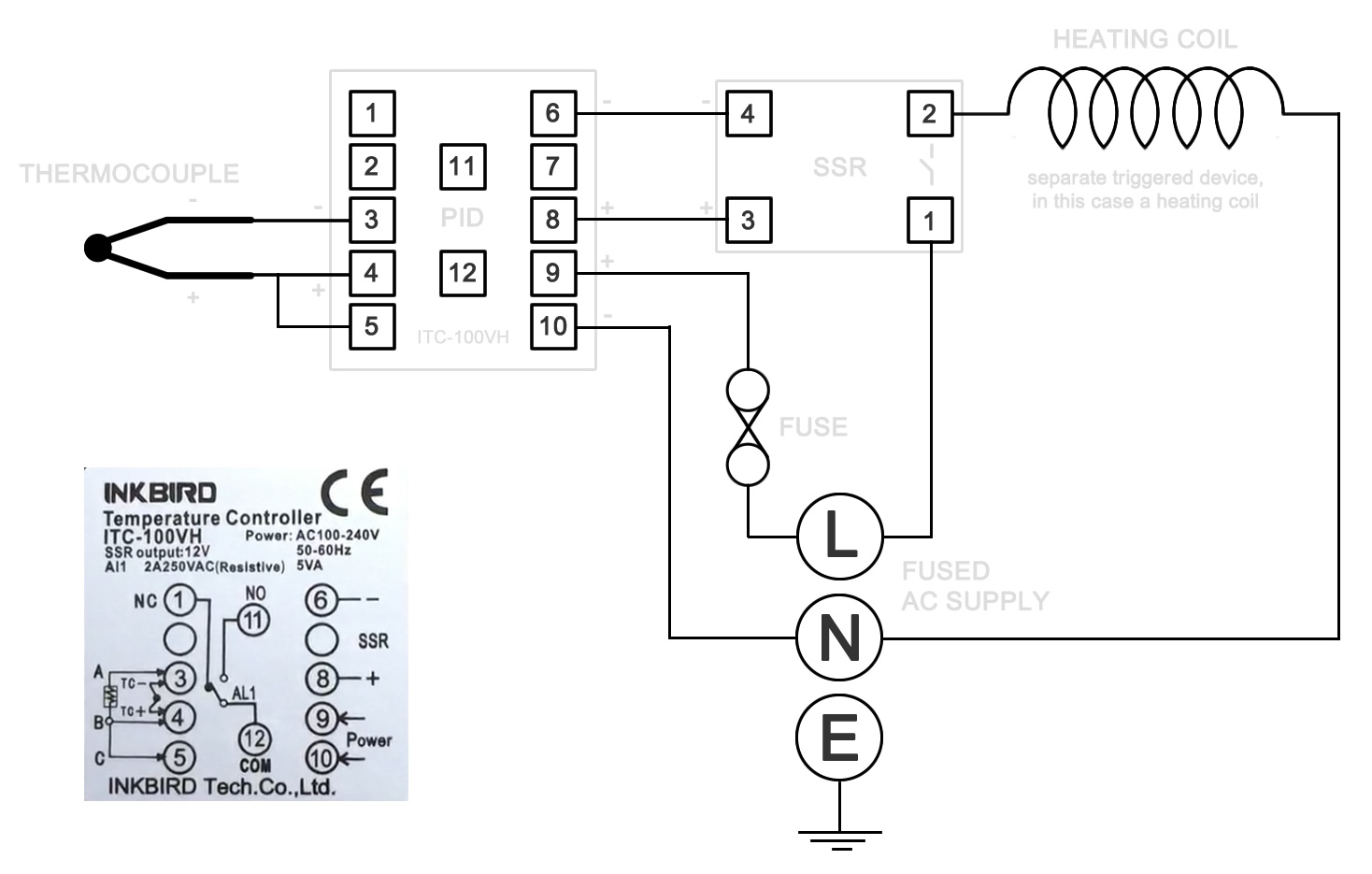
The PID has 12 numbered screw terminals and the silver label diagram shows where the SSR and the Thermocouple are wired to these. However, it's not instantly clear, so I hope this diagram will make things a little clearer.
The power source is the mains in your neck of the woods. In my case I'm in the UK and the standard mains power is 230 volts AC. Wherever you live, you should buy the appropriately rated PID for your area.
The PID itself requires less power than the coils to complete its work, so I’ve included a smaller separate 5 Amp fuse to protect that. An ordinary auto fuse holder can do this for us.
The secondary circuit, the one that's switched on by the relay, is much more demanding. In my case it's a resistance coil which consumes around 10 amps of current and produces 2100 Watts of power. However the whole mains supply is protected using a standard UK 13 Amp fuse, and whilst this technically protects ALL the components, I still think it wise to protect the finer circuitry of the PID with this small fuse.
Possibly the most confusing element of the diagram can be found between terminals 4 and 5 on the PID. Here the manufacturer tells us to bridge these terminals, i.e. run a wire from one to the other. Whilst the first question I asked myself was 'why' I later considered that maybe the same components are used in other items sold by the same company. My advice is to not worry about this and simply bridge the terminals.
Make sure your wires are up to the task. I used a heavy-duty heat resistant flex. It's the sort of cable you might find on any quality extension lead. It's capable of handling the loads placed upon it without risk of overheating. Remember, your wire should be rated higher than your circuit. So if your circuit requires 10 amps, your wire should be able to deliver more.
These fork connectors are great for fixing under these screw terminals and it’s much less fiddly than trying to push in a bare end of cable.
The outside sleeve colour of a wire does not affect the way the wire works. The sleeves are different colours to help make wiring easier. However, if you’re like me, you’ll only have a limited selection of wiring to choose from, but by adding tape in any combinations you desire you can make individual wires. By doing this, you can add a unique wire to every terminal combination. Recording this on your diagram helps keep track of the spaghetti jungle that soon follows.
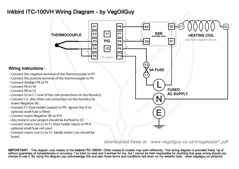
It would be tricky to demonstrate the wiring step by step as it’s such a small area, so I’ve numbered all the points on the diagram like this – and here’s a step by step list if that helps you.
|
I've created some wiring diagram (that you cab see above) for you to download free which you can DOWNLOAD HERE. This includes a step by step wiring guide.
These files are created using Adobe Acrobat Reader which most browsers should already be happy to view, though you may need to download Adobe Reader is you can't view them. It that's the case, just click here (Adobe is a reliable, free service).
Donations -
“For it is in giving that we receive” - Saint Francis of Assisi
If you'd like to offer a donation (and help me fund a few new projects), then please click the donate button below. Payments are handled securely by PayPal. For more information on why I have this button, click here.
|
I made a simple box out of MDF. It’s a little large – deliberately roomy to let the heat out – hence there’s plenty of ventilation holes. The face plate is made out of thin metal with holes cut for the various components.
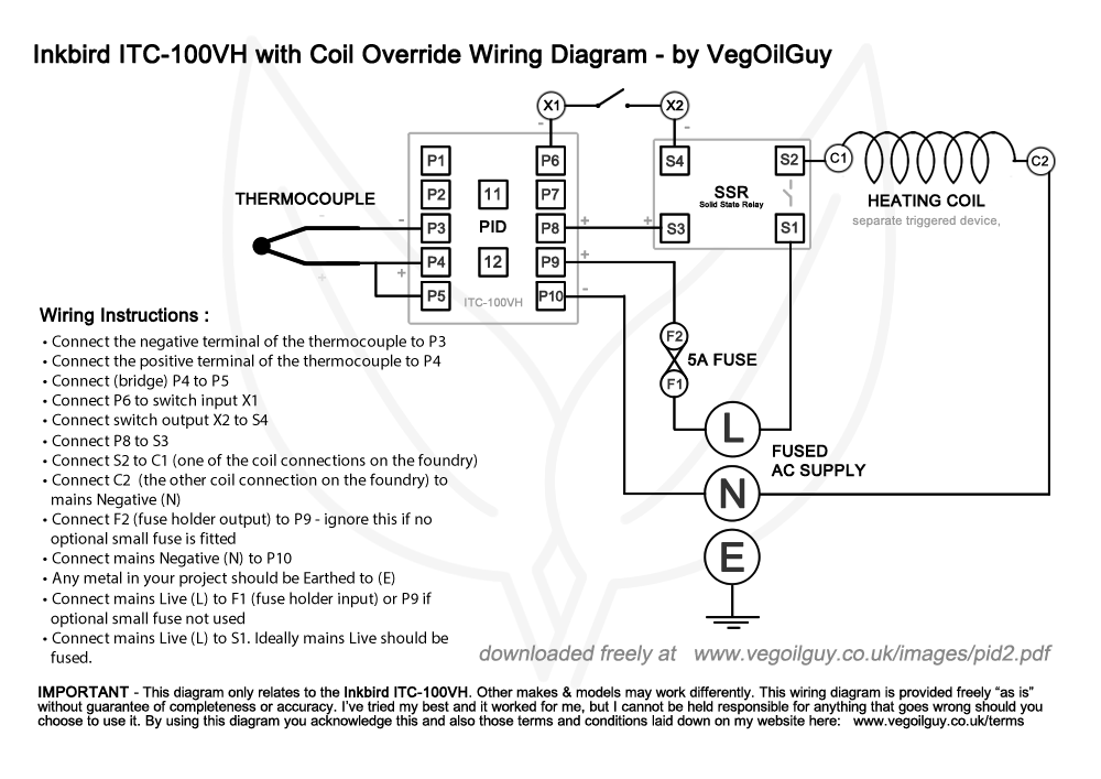
You may notice the third hole. This is for an optional switch. I found that the moment the PID is turned on, the coils activate. For me this wasn’t always convenient. Sometimes I wanted to vary the temperature – maybe to a fairly low level. To facilitate this, I placed a switch between the Solid State Relay connections, interrupting its ability to turn on the coil. For me it’s a useful feature but it’s strictly optional.
|
I've created some wiring diagram (that you cab see above - including my overide switch) for you to download free which you can DOWNLOAD HERE. This includes a step by step wiring guide.
These files are created using Adobe Acrobat Reader which most browsers should already be happy to view, though you may need to download Adobe Reader is you can't view them. It that's the case, just click here (Adobe is a reliable, free service).
Donations -
“There´s nothing more rewarding than giving back and making a difference” - Frank Guzzetta
If you'd like to offer a donation (and help me fund a few new projects), then please click the donate button below. Payments are handled securely by PayPal. For more information on why I have this button, click here.
|
You can download the above image here.
As the face plate is made of metal, it needs earthing. I found a fork connector slid happily under the leg of this PID fixing. I then added a generous dollop of epoxy adhesive on top to keep it in situ.
The box got screwed to the wall near the foundry and the mains cables finally get connected. Power from the 24 volts transformer is fed into the box, through the DPDT switch and on to the motor and the box is finally ready to close.
One more quick tip – a small diagram taped to the lid of the box is a handy reminder of what’s what. It certainly shouldn’t get anywhere near warm enough inside the box to char or burn the paper.
Make sure all the leads to and from the foundry are carefully clipped in place. As the foundry rises and sinks the cables will need to move as well. It’s critical that the cables don’t inadvertently get caught or trapped inside the foundry, so clip everything with care. And keep an eye on these every time you use the foundry. Cables in motion can wear out.
Once the PID is powered up, you’ll need to configure it. This model has a few strange qualities. For instance, the initial temperature setting was way off, about 280 degrees or so if I recall correctly, and that needed changing manually. Then it’s worth running the Auto cycle where the PID learns how to most efficiently control the temperature within the foundry.
But after that, dial in the temperature you want, load up your crucible and sit back. It takes me around 3 hours to melt an A6 crucible of Aluminium at 760 C which is slow, but that’s time I can put to other uses like preparing flasks. I like the convenience, the quiet and the ease of it all. It’s a pleasure to use, genuinely.
And that’s a finished project… a well insulated, electric foundry with an electric hoist.
Just a few important safety issues to consider before finishing off…
Obviously this is a homemade device to hoist very hot material up in the air. There’s a recipe for disaster right there. So before use, always check over all ropes and cables. Any sign of wear, replace immediately. Check all fixing and tighten anything that may have come loose. Make sure the pulleys are secure and working properly. This really is important. If something snaps in mid use, a few smashed bricks could be the very least of your troubles.
This is an indoor project. Water and electricity tend not to get on to well. So if you’re going to build this outside, make sure it’s very well covered. Personally I’d stick with inside.
And whilst we’re working inside, ventilation is also something to think about. Personally I always keep a window open. There’s always a smell involved in melting metals and who knows what kind of gases are escaping. So good ventilation is a good safety precaution.
Wheelchair motors are great and the gearing means the foundry stays up even when there’s no power. Even so, it’s a sensible idea to use a manual safety brace whilst working under the raised foundry. Even a sturdy length of timber will do. Never leave the foundry in the raised position for any length of time – lower it back down as soon as humanly possible.
There’s a fair amount of wood involved here and the heat from the foundry could lead to a potential fire. However, the foundry is well insulated and from my experience doesn’t give that much radiant heat. Certainly I haven’t seen any scorch marks on my wood yet. But I wouldn’t recommend leaving the lid open or the foundry in the hoisted position for any longer than it’s absolutely necessary when it’s running at full temperature as there could then be the potential for excessive radiant heat. So be careful.
With flammability in mind, you’ll note that sometimes I’ve used steel rope and sometime ordinary rope. Whilst I love the strength and heat-resistant qualities of the steel rope, I hate its lack of flexibility and have personally minimised its use to areas of obvious concern, such as right next to the foundry. I’ve leave that choice to you. Just play safe.
It’s well worthwhile at the very least to ALWAYS have a couple of buckets of dry sand nearby to dose any potential fires. Don’t use water as there’s electricity involved here. Ideally a dry powder fire extinguisher should be kept on hand.
Placing a crucible full of hot metal into the foundry needs care and precision. If the foundry is lowered and catches the edge of the crucible, it could potentially spill the content. To help with this, I fitted this simple bracket guide to the base of my foundry. When the crucible is slid it, its bottom should just touch this frame. If it does, I know it’s in a nice safe spot.
Keep a close eye on your crucible. If it appears damaged or thin, don’t use it. Crucible failure happens and it’s most likely to happen when it’s full of molten metal. The design of this foundry should mean that such spilled metal should stay within the foundry and not seep out – but it’s possible so have a smoke detector fitted nearby. Such spilled metal is unlikely to reach the coils as they begin at one brick high in this foundry, but if that occurs the power should immediately cut out – which leads me to my last point.
Finally and very importantly I’m once again going to mention the electrics. Whilst there’s nothing complex here, there’s some major current involved and that can be very hazardous. So please make sure you do things properly. If necessary, ask a competent friend or even a professional for help. Ensure that the supply line is up to code and capable of the task, connected to an RCD (earth leakage device) for added safety. Use quality products, ensure all bare connections are insulated, ground all metal surfaces and protect against wear and tear and heat damage.