Find VegOilGuy on Facebook Find VegOilGuy on Instagram Find VegOilGuy on YouTube
VegOilGuy

Relays in Auto Electrics a basic guide

A Basic Introduction to the Use & Function of Relays

In this auto electrics Tutorial, I’m going to be looking at Relays, their use and function in vehicle electrical circuits. If you're not familiar with relays, you soon will be. The average vehicle is packed full of them and they're extremely useful. Hopefully what follows will give you more than enough information to comfortably understand and use them.

See the accompanying video here...

To begin, if you’ve got absolutely no idea about auto electrics, then see my Auto Electrics 101 tutorial.

What is a Relay?

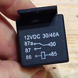
A relay is simply an electronic switch. Their purpose is to switch electrical circuits on and off. They come in different sizes and shapes and usually have 4 or more metal lugs or terminals on them.

Here’s a really simple circuit. There’s a battery, a bulb and a switch.

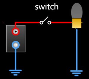
It’s easy to see how when the switch is closed the bulb lights up.

The problem here is, of course, that someone has got to close the switch. What a Relay does is electronically close a switch for you.

Inside a Relay

Relays hold tiny electromagnets. When you place power into them, they created a magnetic field which either attracts or repels a metallic strip that forms the arm of a switch. Historically the standard electronic symbol for a Relay was something like this:

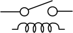
It's easy to see the switch. The coil represents the electromagnet. Imagine that magnet attracting or repelling the arm of the switch above it and you've grasped the workings of a relay.

For this purpose, I’m going to draw my Relays a little differently.

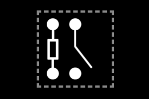
Hopefully it's still obvious which is the magnet and which is the switch. The four large dots represent the terminals of the relay, the small metal lugs that protrude from the plastic shell.
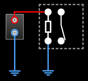
Energising A Relay

To energise the electromagnet inside the relay, it's necessary to connect electric power to the two magnet terminals, in this instance causing the internal switch to close, like this:

So if we wire bulb and a battery to these switched terminals of the relay, it’s easy to see how the relay can be used to switch the bulb on and off.

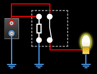
If you've just freaked out, don't... it hasn't suddenly become complicated honestly. Take your time and look what's going on. The only thing that's changed from the previous diagram is the addition of the bulb. The bulb is using the relay as an on/off switch, and this is a relay in its most basic form, what's called a Four Pin Normally Open Relay… four Pins for four terminals and normally open because the switch is open until power is applied to it.

Energise the relay and the switch is closed, lighting the bulb. Disconnect the power to the relay and the bulb and electromagnet turn off.

Open and Closed Relays

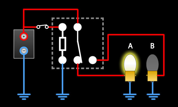
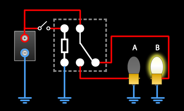
There are different types of relay. We've already mentioned the Normally Open relay, so the first obvious variation is the Normally Closed Relay. At first glance there’s no obvious difference, but the difference lies with the internal switch.

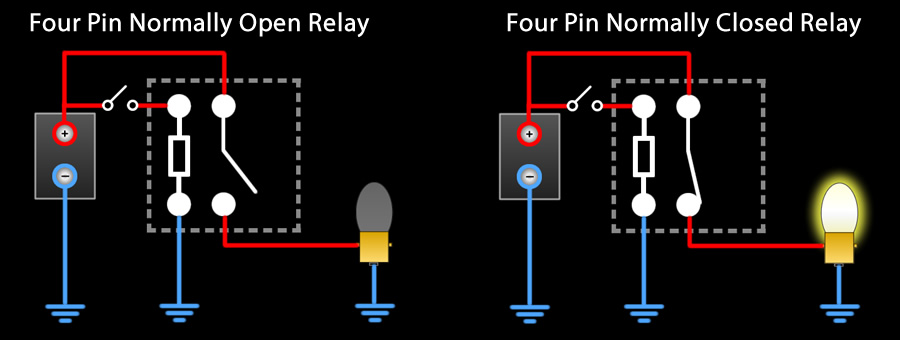
You'll notice in the above diagram that I've introduced what we'll call a master switch into the circuit just before the relay. This master switch will determine whether or not the relay is energised. We can see clearly that when the relay is not energised, when it’s not powered, in a Normally Open Relay the internal switch is open, meaning it cannot power anything (like the bulb). The Normally Closed Relay the internal switch is closed, so this will power the bulb.

Why the difference? Why have a normally open and normally closed? Because sometimes it's useful to have one circuit powered when another is inactive. Imagine a vehicle burglar alarm... you would not want this active whilst the engine was on and you were driving. But when all the other electrics are off and the vehicle is stationary, then that's an ideal time for the alarm to become active, so a normally closed relay might do the job nicely for us... no power energising the electromagnet (engine off) allows the alarm circuits to become powered.

Five Pin Relays

The next variation is a five pin relay.  As the name suggests, with these there’s simply another terminal involved. However this extra terminal gives us a relay that has both a Normally Open and Normally Closed points. This is extremely useful obviously. Personally I tend to only buy five pin Relays as there’s virtually no price difference and a 5 pin can do everything a 4 pin can and a bit more.

For instance, let’s use a 5 pin relay to light bulbs in two separate circuits:

To begin with, notice that the master switch is closed and the relay is energised. The first four pins are acting like a Normally Open relay and the internal relay switch is only closed because the electromagnet is energised. This allows power from the battery to travel through the relay to Bulb A. However Bulb B is connected to the 5th Pin and there's no power there, so Bulb B is unlit.

If the master switch is opened, everything changes:

As the electromagnet is not energised, the internal switch springs open. This now contacts the 5th pin. This means that power from the battery can flow through the relay and light Bulb B. The 4th Pin no longer receives power and thus Bulb A is unlit.

Labeling The Pins

To the best of my knowledge, the Pins on 4 and 5 pin relays are numbered (and lettered) in a universal way. These labels are:

  • 30 - the common switch connection
  • 85 - electromagnet coil
  • 86 - electromagnet coil
  • 87 - Normally Open (NO) Pin
  • 87a - Normally Closed (NC) Pin

Power Handling

Whilst the switching aspect of relays is useful, probably the main feature of them is their ability to handle large amounts of current. That’s why your average vehicle is littered with them. It’s all about the Power.

Generally it takes very little current to energise a relay, and where there’s very little current, the average human can safely handle things. For instance a switch on your dashboard. What you don't want is massive, metal melting power surging millimeters beneath your fingertips. But the tiny amount needed to energise a relay is nice and safe.

Let's use the example of a car horn. These noisy devices can often draw a lot of current. The one on my vehicle is rated at 20 Amps. That's easily enough power to kill a human being.

In the above image, we can see on the left a very bad idea. A high current horn is switched directly from the battery. Yes there's a fuse, but click that switch with a wet finger and you might just do yourself a lot of harm.

The image on the right shows the correct practice and this is the one used by vehicle manufacturers. The switch is used to energies a relay and this only uses a small amount of current and is therefore safe. Meanwhile all the dangerous current is being processed through the relay, operating the horn and isolating you from potential harm.

Different Rating For Different Jobs

Spend a few minutes on eBay or similar sites looking at relays and you'll be amazed how many different sorts there are. Gernerally speaking choosing a relay comes down to:

  • What power is needed to energise the relay
  • What power the relay is expected to handle
  • What switching job(s) are required.

As most vehicles run on 12 volts, auto relays are energised by 12 volts of power. The amount of power they need to handle varies according the the jobs they're doing. Starter motors, for instance, draw hundreds of Amps of power. Lights draw very few. As heavy duty relays are more expensive, it makes sense to choose an appropriate relay for each individual job.

If you look at the picture above, you can see an auto relay. It tells us that it requires 12 volts DC (Direct Current) to energise, which is what most vehicle batterys are. It also tells us it can safely handle between 30 and 40 Amps. So if you wanted to power a 20 Amp circuit, this relay would be ideal, as that's well under the maximum load of the relay. If you wanted to power a circuit of 50 Amps, you'd need a more substantial relay.

Example - Real Life Application

One of my subscribers once asked me how they could connect a 3rd brake light to their vehicle. This could be achieved by simply splicing into the existing circuit brake light circuit and adding another, as shown in the image below on the left. However this this is actually a bad idea.

The correct way to do it is to use a relay, as shown above on the right.

Why? Difference does it make?

In truth a single bulb probably wouldn't make a great deal of difference, but this is about good and bad practice. When it comes to auto electrics, unless you have a very good knowledge of what's going on in the circuit you're splicing into, you really shouldn't overtax it by adding in more components. At best this could blow a fuse but it could potentially lead to burned out wiring and electrical fire, and all because you've added a new component into a circuit that had been finely balanced by the manufacturer.

The safer option was to still splice in, yes, but only to use the power in that circuit the energise a relay. The likelihood of this overtaxing the original circuit is minimal. Now, however, a new fused power supply can be introduced and this can safely power a new light or even a hundred new lights - that's the point! The inclusion of a relay means the older, correctly rated circuit is not in danger of being overloaded and the new circuit is independent, fused and safe.

Helpful Relay Tips

Here's a few handy relay tips:

  • Relays often come with holders. This makes wiring them up much easier.
  • If you’re not using a holder, you’ll either need to solder wires to each terms – which makes removal difficult – or you’ll need Spade Connectors. If you use Spade Connectors:
    • Make sure they’re a nice tight fit.
    • Squeeze with pliers if necessary. You don’t want them coming off.
    • Ideally purchase ones that are fully insulated. If you can't get them, cover everything well with insulation tape. If the come loose, you could easily have a live wire flapping around and that’s never good.
  • Before installation, clean every terminal with fine sand paper. This aids conductivity and ensures a good connection. Once cleaned, lightly brush the terminals with petroleum jelly. You can get proper contact gel and that’s your choice. I’ve found that petroleum jelly is just as good at preventing oxidization, etc, from dirtying the terminals, leading to poor connections and electrical failures.

Summary

That's about all I can think of saying on the subject of relays. They're a safe, practical electronic switch widely used by manufacturers. There are a far greater array available than I've really covered here but they tend to be for specialised applications. The above tutorial is meant to cover the basics.

To help the above sink in, why not try my YouTube video on this same subject:

After not understanding car wiring for the last 4 years, I came across this video. Thank you.

Random YouTube Comment

Donations -

“A generous person will prosper. Whover refreshes others will be refreshed” - Proverbs 11:25
If you'd like to offer a donation (and help me fund a few new projects), then please click the donate button below. Payments are handled securely by PayPal. For more information on why I have this button, click here.

Or... Become A Patron

Alternatively, if you can spare a little each month, consider becoming a Patron. Patron's make it possible for me to continue developing my YouTube Channel and my websites. Please CLICK HERE for more information.