Vehicle Wiring
Things are a little different inside the average vehicle. Typically to reduce the amount of wire needed, manufacturers take advantage of the vehicle being made of metal and effectively use the vehicle body itself as a battery terminal, usually the negative. Let's look at another battery and bulb circuit but this time a vehicle headlight instead of a bulb.
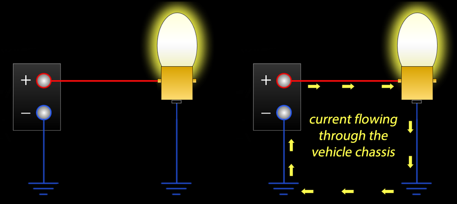
Ignoring switches, relays, fuses, etc for the moment, the above diagram demonstrates how wiring is reduced in a vehicle but still enables current to flow.
- The battery positive terminal is connected to the headlight using a wire. The negative is bolted directly to the chassis of the vehicle, making the whole chassis a negative terminal.
- The second terminal of the headlight is connected to the chassis of vehicle.
- A complete (closed) circuit is created allowing the current to flow from the positive of the battery, down the wire, into and out of the headlight, through the chassis of the vehicle and back into the battery, thus lighting the headlight.
Grounding / Earthing
The process of connecting one of the battery terminals to the vehicle chassis is known in auto electrics as grounding or earthing:
- As previously stated, it's usually the negative terminal that's grounded but not always, so be sure to check each vehicle individually.
- Some vehicles have fiberglass bodywork and do not adopt this process at all. So for every positive wire, there will be a negative wire.
- It's also worth noting that in residential wiring grounding / earthing is something quite different and should not be confused. It such situations there are usually three terminals, positive, negative and earth - with the earth being a safety feature. Please keep this is mind and don't mix up residential and auto electrics.
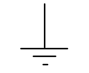
When shown in an electrical diagram, grounding is usually depicted by this symbol:
So let's look at the bulb and battery circuit again, but this time we'll make use and grounding to reduce wiring and we'll display this with the appropriate symbol.
Once you know this symbol, it becomes much easier to understand auto electrical diagrams. I've used arrows once again to help demonstrate current flowing through the circuit. Even though there's no visible connection between the two negative elements in this circuit, it can be assumed that current flows uninterrupted through the chassis.
Fuses
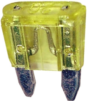 Just like in a property, vehicles have fuse boxes and inside these are an array of fuses of different values. Fuses are an important safety.
When things go wrong electrically, more electric power (current) can be drawn than is safe. If this power meets electrical equipment, wiring or even people, it could cause a great deal of damage. The job of a fuse is to only allow a certain amount of current through it.
Think of a fuse as a doorway. A narrow doorway will allow a few people to walk through untroubled. But if lots of people try to force their way through the doorway at the same time, then it will overload the doorway - it will be unable to cope - and the doorway could well collapse altogether, blocking the pathway and preventing anyone from passing through.
Whether a doorway would really collapse or not is debatable, but a fuse certainly does. A fuse will allow up to a certain amount of current to pass through it but if more tries, it "burns out" and ceases to work, preventing any more current passing through.
Fuses In A Circuit
Let's look at a fuse in our bulb circuit.
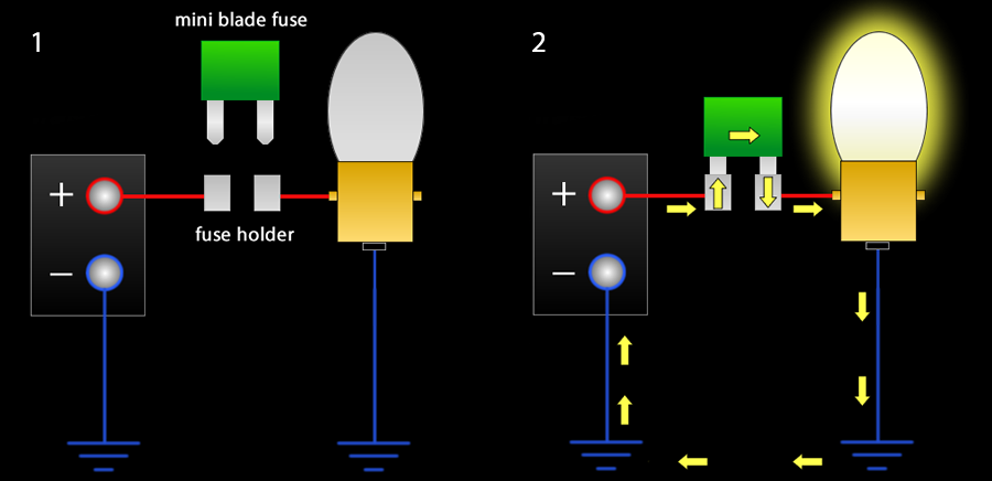
- Our positive wire is now interrupted by a fuse holder. This breaks open the circuit creating a gap that only the fuse can fill. Because of this the current cannot flow and the bulb is not lit.
- When the fuse is correctly fitted to its holder, the circuit is closed (complete) and the current can now flow, lighting the bulb.
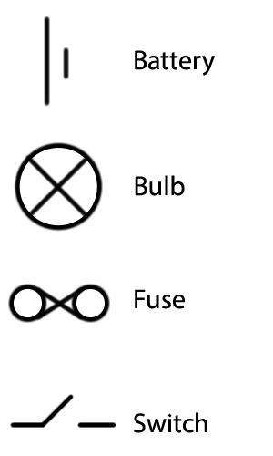
More Symbols
As I've introduced the concept of symbols when mentioning grounding, it only seems appropriate to demonstrate the symbols associated with the other elements mentioned on this page:
Switches
Something I haven't made mention of yet is switches, but that's because we're all so used to them. Just about everything electronic needs turning on or off using a switch and your average vehicle is packed full of switches. The symbol for a switch looks like a broken straight line and that's exactly what a switch is - it's a break in an electrical connection. When a switch is open, there's a broken connection and no current can flow. Closing the switch makes the connection and allows current to flow.
Symbols In Use
So if we display the battery, bulb, switch and fuse circuit using appropriate electronic symbols we'll get something like this:
The straight lines that connect the components are wires. Wires are always displayed in straight lines even though in real life they're usually anything but straight. Hopefully you can see at the far left is the battery connected to the chassis, with a positive wire to the switch. After the switch comes the fuse. The fuse has a wire to the bulb and the bulb is then connected to the chassis, completing the circuit.
It's also worth mentioning that the symbols for switch, fuse and battery can appear rotated ninety degrees to how they're shown here. Similarly the circuit could be drawn differently. That doesn't really matter. As long as you understand these basic components and what they do, you'll be well on your way to better understanding auto electrics.
Summary
I think that will do for a basic introduction the auto electrics. We've seen how most vehicles get their power from a 12 volt battery. Most vehicles ground the negative terminal of the battery to the chassis of the vehicle. Fuses are used throughout vehicles as a safety device. We've also covered the basic symbols and hopefully kept things easy enough for all to follow.
More tutorials will follow later building on this fundamental beginning.
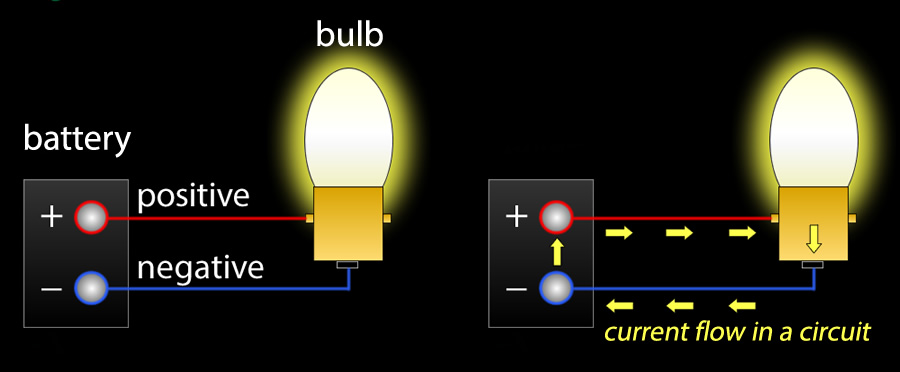
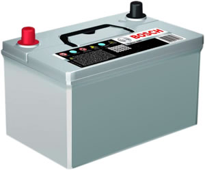 The source of electricity in most vehicles is of course a Battery. In the vast majority of modern vehicles this battery is 12 volts (older models, motorbikes, unique builds, etc, can be different). This means that most of the items within the vehicle are designed to function on 12 volts.
 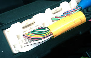 The power from the battery is carried to the electrical items via wires, which are strands of copper wrapped in a coloured sleeve. There are hundreds if not thousands of wires in the average vehicle and if the vehicle body, interior, engine, etc, magically disappeared leaving only the wires, what you'd see would probably look a little like a spider's web.