The Easy Way to make Caterpillar / Continuous / Tank Tracks at Home
Caterpillar tracks - continuous track - dozer tracks - tank tracks - whatever you call it, I've always had a fascination with it; that incredible ability to go places other vehicles can't go - massive grip and minimal ground pressure thanks to the large surface area of the track itself.
When I decided to have a go at making a fairly large model track (about 3ft / 1meter approx.), I was disappointed at the complexity of some designs I found, way beyond the limitations of my basic tools. This meant I had to come up with another method - an easy way to make caterpillar tracks.
This is what we're making - a set of continuous tracks
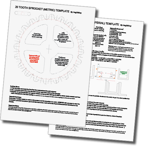
FREE PLANS - DOWNLOAD HERE
I've created some free plans to go along with this build. They will allow you to print a sprocket template, provide you with measurements and list the materials required. I've done my best but I'm no engineer...
These files are just Zipped PDFs. But you'll need to download, unzip and read (and print) using Adobe Acrobat Reader.
There's a choice of two - one showing Inches and one showing Millimetres, show choose your preference.
Instructions : Just click the relevant link above. In most browsers I believe the folders will automatically download. If not, you may need to choose to Save the folder first. You will need to unzip the contents and Adobe Acrobat to read the PDFs. Any problems, get it touch. Enjoy!
Donations -
“True generosity is an offering given freely” - Suze Orman
If you'd like to offer a donation (and help me fund a few new projects), then please click the donate button below. Payments are handled securely by PayPal. For more information on why I have this button, click here.
Inspiration
I believe in giving credit where it's due and my initial inspiration came from watching a video by Matthias Wandel on his excellent website. Have a look for yourself to see what I mean - woodgears.ca/tracked_vehicle
I loved Matthias' simple approach and even toyed with the idea of using wood myself. But I wanted something a little more robust so metal was my preference, though the idea of making all those complex joints terrified me. Steel would be incredibly resilient but hard to work, expensive and heavy, so I opted for aluminium.
Aluminium Profiles
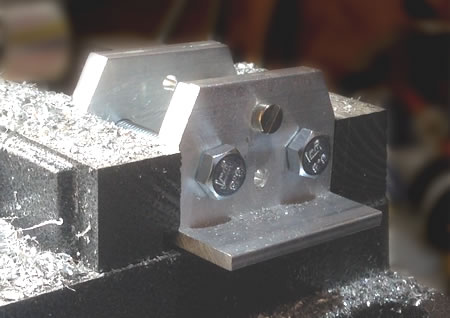
The moment I started thinking about aluminium it occurred to me that there were all manner of profiles (shapes) available, including box section, L, U, T and all manner of other specialised shapes. Looking online at one particular website, I noted the dimensions of various profiles and had one of those Eureka moments. I headed off to the local DIY store and purchased some much smaller sections to produce this mock-up:
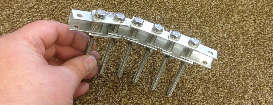
My original prototype - two size of U channel link together to form a chain
If you look closely you can see there's a series of rectangular pieces connected together with nuts and bolts. Crucially there's two sizes of U channel involved, one of which fits neatly inside the other. This meant it was possible to make a flexible metal chain using off-the-shelf supplies and ordinary tools.
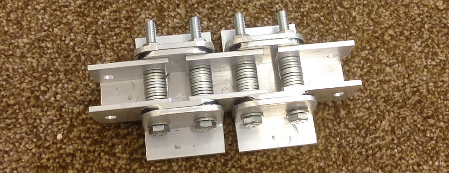
I then went on to make this mock-up that might look a little more like continuous track:
My second mock-up - continuous track concept
This is, of course, just 2 links in a track of approximately 40 or more but it was simple engineering. Whilst it might look a little more complex, it's exactly the same. The only differences are the use of larger U channel and the addition of some L channel stock.
Continuous Track - What's Involved?
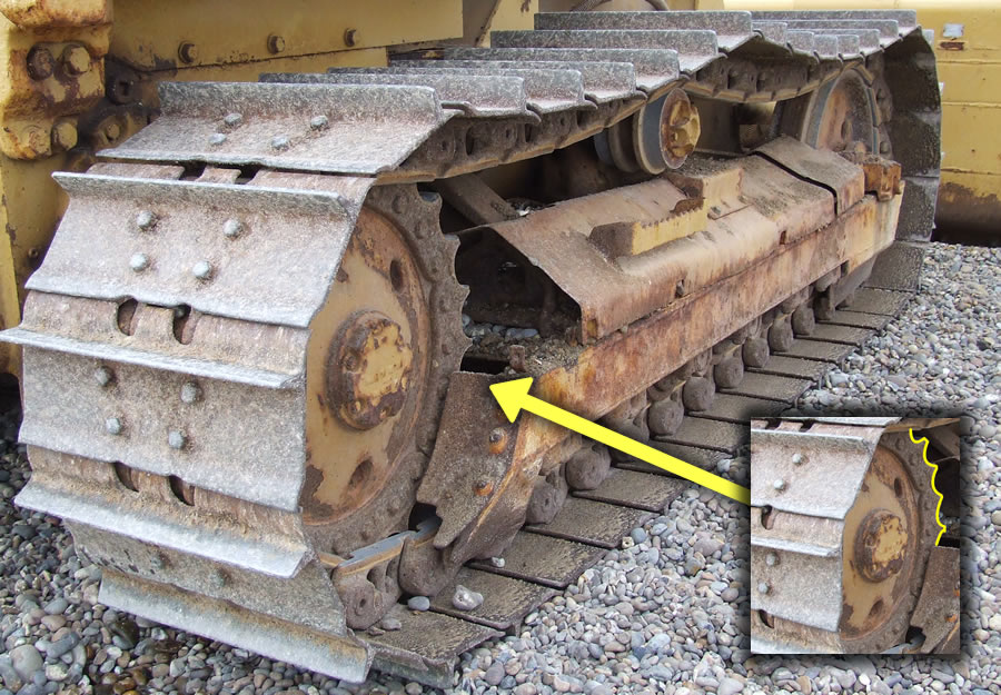
If you've watched Matthias' video (and you should) you'll see he constructed a wooden sprocket with teeth that bite into (and therefore drive) a wooden chain. Now look at this image of an actual track:
Actual continuous track - see the sprocket at the front (left)
At the front left you can clearly see a large sprocket that Matthias cleverly emulated. Just like in Matthias' example, the teeth of the sprocket interact with the chain (the track) and propel the vehicle.
If you're thinking this is all new to you, some unknown alien technology, you'll be surprised how common the sprocket and chain combination is. How about an ordinary bicycle? The sprocket is the bit you pedal and the chain drives the wheel.
To produce something similar it's necessary to build two elements, a sprocket (the drive wheel) and a chain (the track). This would normally involve some complex machining, but thankfully there's an easier way.
Making A Chain By Combining Profiles
As I've already hinted at above, by carefully selecting profiles, I was able to purchase sections that would slot together to form a basic chain. If I haven't made this point clear enough until now, the chain and the track are the same thing, so in making a chain we're making a track.
Combining profiles to make a track (cross section)
I chose two U section profiles and critically the smaller fitted perfectly inside the larger. There are minor variances involved in manufacture but I reasoned that even a moderate amount of filing down would be easier than trying to cast or machine my own fittings and as it turned out I was right.
To add some width to the track I decided to incorporate two L sections. These come in a variety of sizes but I kept mine quite small.
The profiles are produced in long lengths and it's obviously necessary to cut these down into smaller section. The size of these smaller sections, the links in the chain, is determined by the sprocket.
Sprocket
I wanted to make my sprocket from aluminium and I have already covered this in detail elsewhere on this website. For that you'll need to look at:
In short I took scrap aluminium in the form of ordinary soda cans and melted this down in my home made foundry to form ingots. I decided on the dimensions of my sprocket and created a wooden template. From there I was able to quickly reproduce copies of the sprocket made from Extruded Polystyrene Foam. Through lost foam casting, I was able to pour molten aluminium into a sand mould and convert the foam into a solid, usable sprocket - four of them in fact.
If the above sounds daunting to you, you really should look up the pages and videos I've suggested. Lost foam casting at home is remarkably easy and readily affordable. In many ways it's not much different to using an ordinary barbecue.
Sprocket Dimensions
The dimensions of the sprocket define everything that follows. There's four main factors that effect the overall size and shape of a sprocket. There's number of teeth, the diameter of the sprocket, the gap between the teeth (the link length in Matthias' program) and the diameter of the roller.
Sprocket chains generally incorporate a free-turning roller. If you go back to the images of my prototypes, you'll see I've used a let of washers. These make great, cheap but effective rollers.
I had two things in mind, the gap (which I wanted to be 25mm / 1 inch for simplicity) and the diameter that I wanted to be roughly between 150 & 200mm (6 and 8 inches). The roller size was the diameter of the washers I planned on using, this being 12mm (half and inch).
As I've mentioned elsewhere on this site, Matthias's excellent Sprocket & Gear program makes calculating all the factors involved extremely easy. I simply fed in these figures and it produced a sprocket diagram for me to print and build a template from. Brilliant!
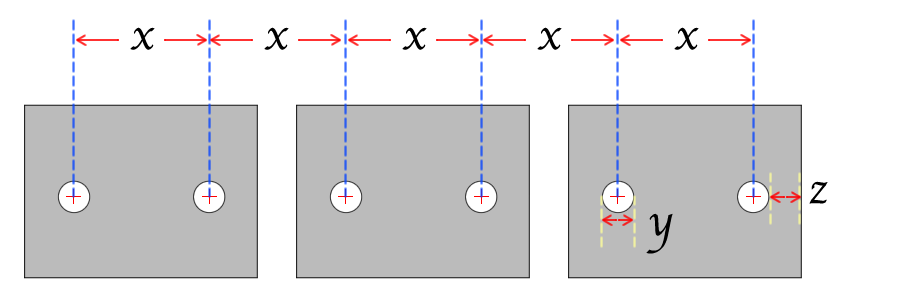
The size of the gap is something you decide for yourself. I've shown this measurement as X in the image below and for me this measurement was exactly 25mm (1 inch), but that choice is yours.
The gap between the teeth of the sprocket (left) X has to be reproduced exactly on each link of the chain (right)
On the right of the above image is a side view of a link (a piece of the U channel). You can see the relationship of the measurement X between the sprocket and the link. And this relationship has a direct effect upon the chain (track) itself:
Three links of the chain each X apart. This helps define the size of each link.
Boring Maths Bit
To determine the size of the link we need to know:
X - the gap between the teeth of the sprocket This is your choice - your personal preference
Y - the diameter of the holes drilled Bolts will act as pivot points in the link so holes are required
Z - the amount of material to the edge The larger the better as strength is needed to prevent the material ripping. But we're limited by the overall size of the links in the chain
So to calculate the overall length of a link we'd do the following:
Link Length = X + Y + 2Z
My X was 25mm (1 inch) as previously stated. My Y was 6mm (1/4 inch) as this is a nice bolt size, not too big and not too small - plus they're readily available. Z in many ways is as big as you can get away with whilst leaving space between the links for movement. I went with 7mm (1/4 inch). This meant my links were 25 + 6 + (2 x 7) = 45mm in length.
Mass Production
Once the length is known, it then becomes a case a doing a lot of repetitive cutting, and I mean a lot... several hundred cuts. From the large and small U channel pieces, I'd estimated I'd need around 80 of each, plus I wanted at least 10 more for spares (or errors). That meant 90 of each U channel. The L shapes sit either side of the large U, so I needed twice as many of those making it 180 (with spares).
Now this is garden-shed engineering so the chances of getting every single cut to be identical is remote but it's important to try as wild variations will prevent the track from ever working.
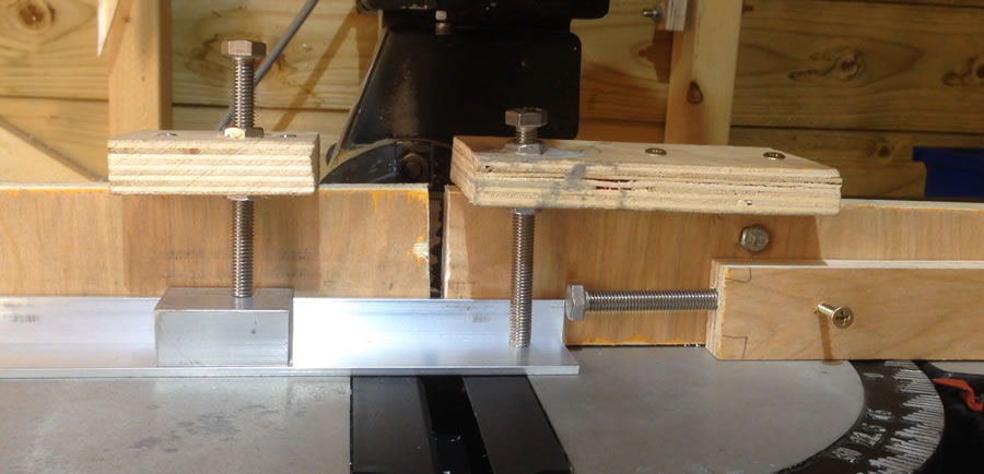
Jig Time
To cut the pieces, I opted to use a standard electric mitre saw. With an appropriate blade in them, they make light work of aluminium and produce a nice straight finish.
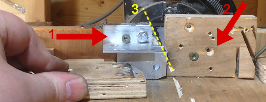
To get each cut as close as possible in size I set up a simple jig. This consisted of a wooden fence bolted to my saw and a bolt 'stop' to gauge length (the bolt allows for fine tuning of length). I also attached a few home made clamps to secure the aluminium whilst cutting.
The deck of my mitre saw - note the adjustable bolt / stop (lower right) and the home made clamps securing the aluminium
The stopping, clamping, cutting, repeating process bored me senseless - but it's necessary to keep all the pieces the same size - so don't skimp or rush.
Once cut, it's a good idea to run a file along all the cut edges to remove any burs.
There's a few jigs needed to complete this project and the ones I'm showing here are really the minimum level you should use. Take your time in constructing jigs. Make them accurate and secure. The more precise your jigs, the better your results will be.
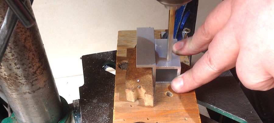
More Boring
If cutting bored you then the next part will really sink your boat as it's necessary to drill two holes in every single piece. What's more the position of the holes is critical to ensure the chain and sprocket effect works properly. If ever jigs were needed it's here.
Calculating the position of the drilling points
In the above diagram you can see on the left the small and large U channel links. On the right you can see how the smaller piece fits inside the larger and the positions of the holes. As the smaller pieces rests on the larger piece we need to know the thickness of material, shown in the diagram as W - which for me was 3mm (1/8 inch). We already know Y (the size of the hole we're drilling) and Z (the distance to the edge) so distance A = Z + Y/2. So for me this was 7 + (6/2) = 10mm. Thus A is 10mm and that represents the distance from either edge to the drilling point.
Calculating B is much easier... it's pretty much up to you. As long as you take into account W (the thickness of the material) and leave plenty of space around the hole Y then you're okay. I knew I wanted to add 12mm (half inch) washers to my bolts to act as rollers (more about that later) and so I decided that B would be 15mm (5/8 inch).
Knowing the drilling points is one thing, but consistently drilling them into each piece is another. I think without a drill press this would be very difficult so if you haven't got one, you might want to hire or borrow one for this project.
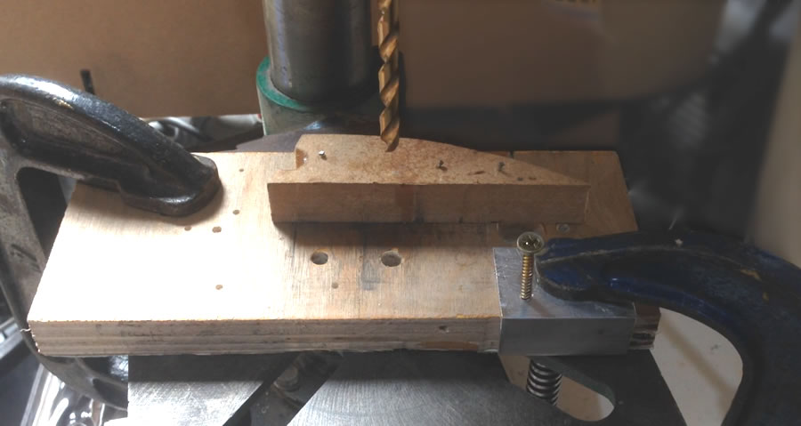
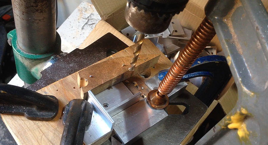
Large U Drilling Jig
Crude drill press jig for larger U channel - a back rest, a stop and ample clamp support
In the above image you can see the very basic jig I clamped to the table of my drill press for the larger U channel. At the rear you can see a very-scrap piece of MDF which acts as a back rest and on the right you can see a small metal tab which acts as a 'stop.' As crude as this is it's still quite tricky to set up and don't be surprised if you waste a few of those spare pieces you're now glad I had you cut.
Crude drill press jig - but it allows for consistent positioning
You can see above how the jig aligns the drill point on one side of the piece. Once drilled, the piece can be rotated and so the drilling point appears on the other side - allowing for two holes to be drilled. As long as the lengths of pieces are consistent, this will work fine.
This jig is too crude if I'm honest. You'll be drilling a lot of holes and mistakes can slip in so the more supportive you can make your jig the better.
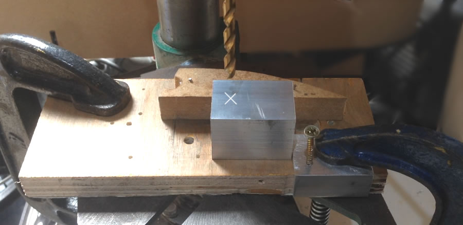
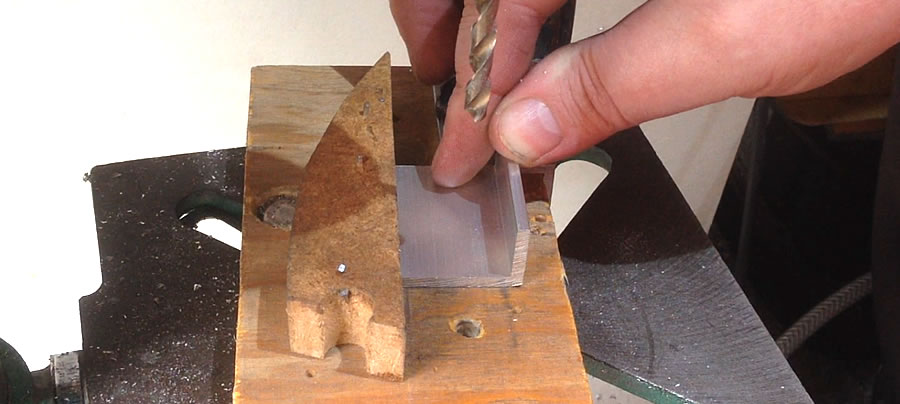
Small U Drilling Jig
Small U Jig - everything's the same but note the aluminium strip on the back rest
Above you can see the same jig from a different angle, but this time it's being used for the smaller U channel. To compensate for the depth of the material (W) a scrap piece of the L channel is secured against the back rest. Other than that, it's just more of the same - drilling, flipping, drilling again.
L Shape Drill Jig (1)
L Shape Jig - the same jig (without the aluminium back rest) works fine for the left hand hole
Still using the same jig but this time without the metal back rest, the left side hole of the L pieces can be drilled. However, if we flip the piece over it cannot lie flat. This means we can't drill the right hand side without structural changes.
L Shape Drill Jig (2)
L Shape Jig Right Hole - same back rest but the stop repositioned to the left and additional front support
For the right hand side, I kept the existing back rest but positioned a 'stop' on the left hand side. Furthermore I added a supporting piece to the front. This meant that each piece was supported on 3 sides making it fairly stable, though ideally the work should be securely clamped - so if you can achieve that in your jigs, do so. The better the jig, the better your results will be.
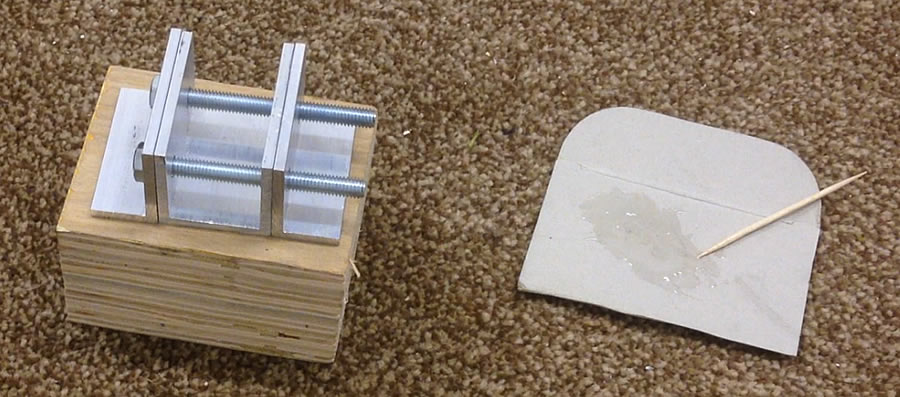
Gluing Time
This is an optional step but one that you may find helpful. After initially dry-fitting all the pieces and de-burring them, I decided to adhere the large Y and and L's using a strong epoxy adhesive.
Following a dry fit, the large U and L's are bonded with epoxy adhesive
Bolts are used to ensure alignment and the pieces rest on a flat block whilst drying to make certain the bottom of each track section is nice and flat.
Gluing helps in handling for the further machine work that's coming up.
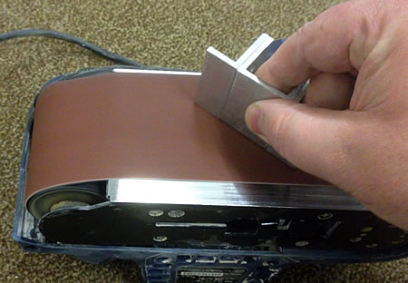
Alignment
Hopefully if you've been careful with cutting and drilling everything should align perfectly. If, however, some minor imperfection have crept in, now is a good time to remove these. I found an ordinary belt sander made easy work of this.
Make sure the belt is spinning away from you. If you lose your grip and something comes flying off, it's best this goes in the opposite direction. And if you notice the piece getting excessively hot, the chances are you need to change your sanding belt.
Allowing For Movement
To enable the links to move, it's necessary to trim some sections off, particularly the corners. Again the mitre saw with an appropriate blade is the ideal tool for the job.
Corners need to be trimmed to allow for movement
I found that an angle of 25 degrees worked nicely. This allowed for the level of movement I required whilst not taking away too much material.
Of course trimming a small piece of metal from a piece of already quite small metal is more than a little dangerous when using a mitre saw, so jigs are once again essential.
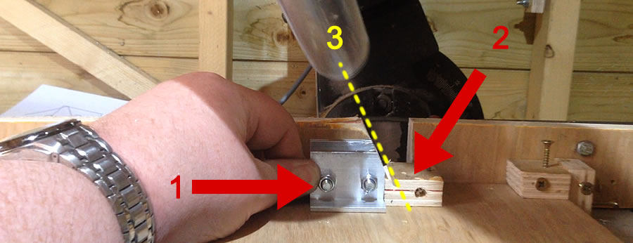
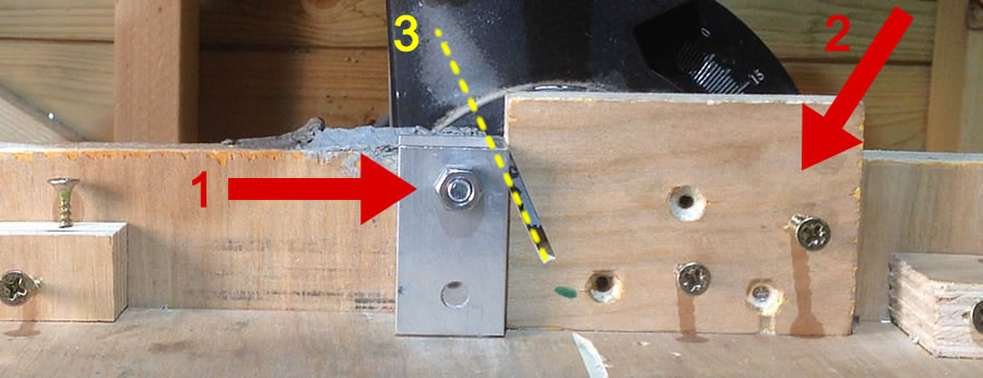
Trimming the large pieces: 1) Even though glue is applied, it's best to lightly tighten bolts in place to prevent the force of the blade smashing everything apart. 2) A stop block ensures accuracy. 3) The angle of cut. My fingers are very close to the blade so concentration is a must. Use a firm stick to hold / apply gentle pressure if you prefer.Trimming the smaller U bottom edge: 1) A bolt is secured into the fence and the piece is suspended in place - you could use two bolts for added security. 2) A stop block ensures accuracy. 3) Angle of cut.Trimming the smaller U upper edge: 1) The bolt is re-purposed to secure an upper bracket holding the work on the deck. 2) A stop block ensures accuracy. 3) Angle of cut. Note that this time I used a scrap of wood to hold the work in place during cutting.
Optional - More Fixings
I do tend to be a belt and braces kind of guy and to reduce the likelihood of rattling I decided to assist the glue with some permanent fixings. I managed to find some small bolts which were actually advertised as Mecanno compatible, so that should give you a clue how small they were. I bored four 3.5mm holes into each main section and tapped each hole with a M4 thread. This enabled the bolt to screw into the work itself. The addition of a little Thread Lock (a paste that stops bolts coming loose) helped secure things nicely.
Optional - Rounding Corners
Using the belt sander again, I opted to round over the corners. My logic was that if anything was going to snag it would be a sharp corner, so by rounding these out I hoped to avoid such a problem. Plus, to me at least, it improved the look of things. In truth it doesn't really matter.
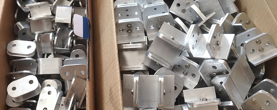
Two boxes filled with fittings ready for assembly. Notice the corners have been rounded..
The angles of the cuts meant such corners should not theoretically clash, so I'll leave this as an optional be of extra work. And thankfully we're now ready for assembly.
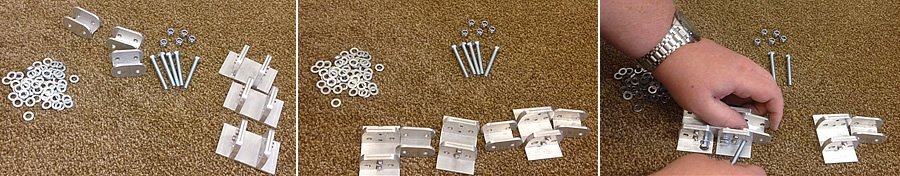
Assembly
Assembly is easy though it can be a little fiddly. It's simply a matter of beginning with one fitting, say the larger link (on the right in the above image) and inserting into this the smaller fitting (on the left). A bolt and washers secure the intersection and a nylon (locking) nut is tightened but not fully. A small gap is left, sufficient to allow the bolt to rotate freely whilst still hold everything securely. This is critical to ensure smooth and free movement of each link. Then another piece is added (the larger), then the next (smaller) and so on, forming an interlocked chain.
Assembly is simple enough... big, small, big, small... interlace and bolt
Washers / Rollers
In a sprocket and chain arrangement, the chain generally incorporates rollers. Rollers can be purchased but they tend to be expensive and are lend themselves to more precise engineering then is evident here. However a roller is needed and its the use of washers that makes this possible. Because the washers sit quite loosely on each bolt, they allow for slight intolerances in the build. Plus they're very cheap and wonderfully effective - a true win-win situation.
Inserting the washers that form the rollers can be very fiddly. My fat fingers struggled this this. But here’s a handy tip that will save your sanity. Count out the number of washers you need and place them on a spare bolt. These should fit comfortably between the gap of the smaller U channel. Using tape, enclose all the washers and leave a scraggy end to make removal easier.
This roll of washers is much easier to insert. Slide the bolt through, add a washer and a nut, then repeat the process.
Finishing The Loop
If you begin with a large section, you should end with a small section, so these two can be connected to form the loop of the track. Counting only the larger sections (for convenience), each track in my case was made up of 40 connected links and you should, of course, have two tracks.
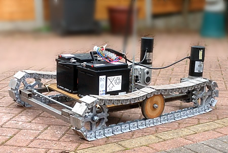
And that's pretty much it... you should now have a set of tracks.
I made a frame from 1 inch (25mm) square box steel, added a couple of wheelchair motors and two car batteries to power them. With everything fitted securely, I was able to test the track and it worked a treat.
One thing I realised as I put mine together was that the track really did need supporting in the centre. As I was keen to test, I quickly produced a couple of wheels from MDF, not the best choice of material but it was an ideal thickness that matched the sprocket. I will be casting a couple of wheels, maybe four… I haven’t made my mind up. These don’t need to be sprockets. Round will suffice.
Aluminium Longevity
Will these tracks last forever? Of course not. If I wanted heavy duty usage, I’d have gone with steel. But with that said at the time of writing this article I'd probably got 20 hours of play on my tracks. Obviously there are light scratches where the track meets the ground plus plenty of dirt (which I regularly brush off before spraying the track with a dry lubricant). But otherwise there’s no sign of wear.
Obviously I'll keep you informed. Check this page again for updates... hopefully there won't be any.
“Generosity isn´t an act. It´s a way of life” - Chip Ingram
If you'd like to offer a donation (and help me fund a few new projects), then please click the donate button below. Payments are handled securely by PayPal. For more information on why I have this button, click here.
Or... Become A Patron
Alternatively, if you can spare a little each month, consider becoming a Patron. Patron's make it possible for me to continue developing my YouTube Channel and my websites. Please CLICK HERE for more information.
 Caterpillar tracks - continuous track - dozer tracks - tank tracks - whatever you call it, I've always had a fascination with it; that incredible ability to go places other vehicles can't go - massive grip and minimal ground pressure thanks to the large surface area of the track itself.
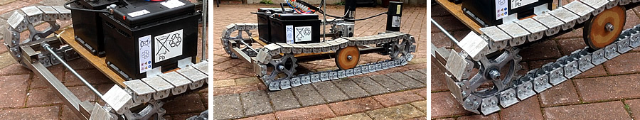
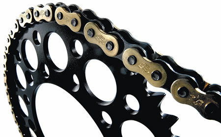 If you're thinking this is all new to you, some unknown alien technology, you'll be surprised how common the sprocket and chain combination is. How about an ordinary bicycle? The sprocket is the bit you pedal and the chain drives the wheel.
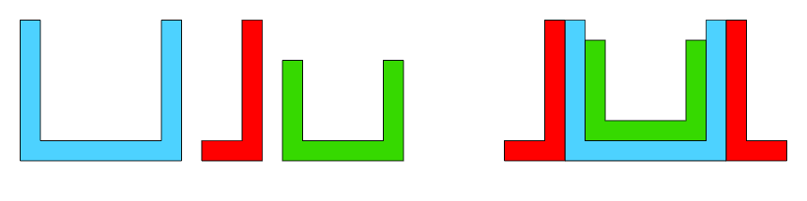
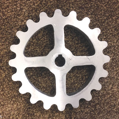 I wanted to make my sprocket from aluminium and I have already covered this in detail elsewhere on this website. For that you'll need to look at:
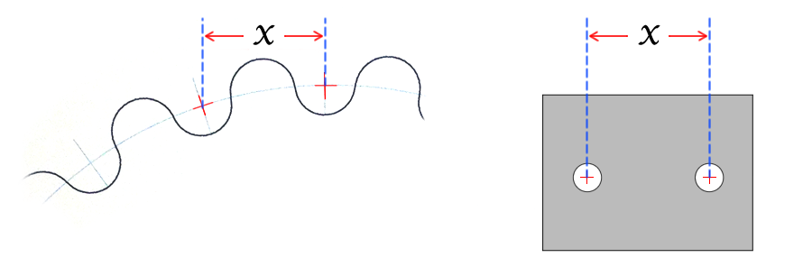

 Hopefully if you've been careful with cutting and drilling everything should align perfectly. If, however, some minor imperfection have crept in, now is a good time to remove these. I found an ordinary belt sander made easy work of this.
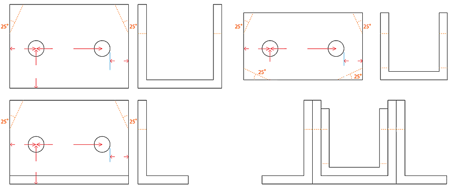
 I do tend to be a belt and braces kind of guy and to reduce the likelihood of rattling I decided to assist the glue with some permanent fixings. I managed to find some small bolts which were actually advertised as Mecanno compatible, so that should give you a clue how small they were. I bored four 3.5mm holes into each main section and tapped each hole with a M4 thread. This enabled the bolt to screw into the work itself. The addition of a little Thread Lock (a paste that stops bolts coming loose) helped secure things nicely.