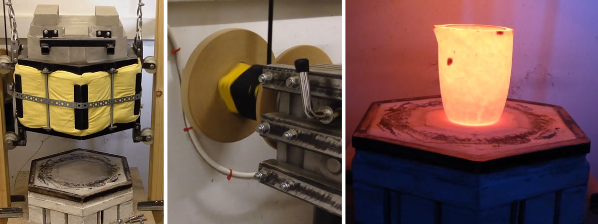
However, it needs to be understood, they're not fast. If you want fast, stick with gas, oil or solid fuel. But if you're the patient sort, probably the biggest bonus of an electric foundry is effeiciency... you can dial in an exact temperature and get there without wasted energy, though it can take a few hours.
Inspiration
Seeking inspiration I turned to the internet and found an excellent series of videos by TAOW on YouTube. I was so impressed by these that I would urge anyone with an interest to watch them - here.
Rough Design
TAOW's approach was excellent and I learned a lot. I'd have been happy to copy his design exactly but unfortunately it was just too small for my personal needs. TAOW took four high temperature insulation bricks and stood these on end, forming a square void for the foundry chamber. This was a great approach and minimised the bricks needed. But I needed bigger and the next best thing for me involved a hexagonal design. This increased the volume of the foundry by almost double and made better use of the bricks depth for insulation, but it does require a lot more bricks.
Insulating Bricks
I realised I'd need 18 bricks to form the main body of the foundry, this being 3 rows of 6, plus a similar row to insulate the base, making a total of 24 bricks. When ordering I purchased a nice round 30 as I know what I'm like and in hindsight I'm glad I did.
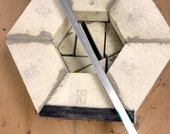
The bricks were Grade 28 Insulating Fire Bricks as these aren't cheap. At the time of purchase they were £5 each. However they're a specialised item capable of withstanding temperatures of 1500°C / 2732°F. They're regarded as lightweight though when there's 30 of them it's still a two-person lift.
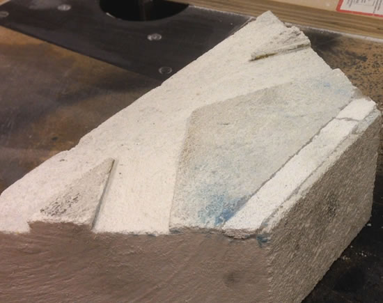
Cutting
Bricks are generally rectangular in shape and to achieve my hexagonal shape I needed to remove two 30° slices from each brick. The company I purchased the blocks from were happy to provide a cutting service at £5 per cut, effectively making each brick £15 each. You can imagine what I told them.
Fortunately I found a very simple way of cutting the blocks and saved myself £240. You can see my firebrick cutting guide here.
Table
This is an indoor project and a stationary one, so having cut my bricks I set about making a sturdy wooden table. It's fixed to the wall and solid enough to take even my hefty weight. It's not strictly necessary to build a table. You could build straight off the floor. But it makes sensed when dealing with dangerous temperatures to work as comfortably as possible. So whilst this table is quite short, it's custom made to a comfortable working height for me.
Off-Cut Base
Loosely arranging the bricks on the table inspired me to make the first use of my off-cuts and I decided to double the depth of my base. I drew a pencil line around the shape then arranged some of the off-cuts into a similar shape. There are lots of air gaps but air is an excellent insulator, the gaps are quite small and overall there's plenty of strength there to support upper layers.
I decided to bond these in place using ordinary expanding glue. This wouldn't survive any moderate heat, but this low down has proven to stay perfectly cool, I'm pleased to say.
Brick Base
With the cut-offs stuck in place, I then bonded a row of bricks on top of these. For this I used a specialised high temperature mortar specifically intended for use in a kiln where electric coils were present. I bought mine from the supplier of the bricks and it's important to get the right sort as some mortars can corrode the coils.
When it comes to mortarting I eventually found a useful technique...
Mortar Technique
 Take a small amount of the mortar and add this to a separate container. Add plenty of water and mix until you have a very liquid mortar mix. This can then be painted on to the brick surfaces where thicker mortar will momentarily be applied. As the bricks are so absorbent, they suck the moisture from the mortar almost too quickly for my liking. Priming the surfaces in this way gives you slightly more working time and, for me at least, a better bond.
Once primed, take the original (unthinned) mortar and apply this very thinly to both mating surfaces. I found I could literally scrape in on and scrape it off again. Too much mortar is, I'm given to understand, a mistake.
At this stage only the outer row of bricks were laid. The centre was left hollow to allow for clamps to be used later.
I allowed the base to sit a good day to dry firmly and then I checked for flatness and level. I wanted to ensure the base was very flat and my hands told me there were imperfections. I tackled these with a combination of a rasp and some coarse sandpaper stuck to a board.
First Frame
There's a fair bit of welding in this project and I'm no welder. I'm still learning and both my equipment and welding talent are on the cheap side. But it is possible, even for me, so don't be afraid to try it if you never have.
I took some 30mm (1 3/8 inch) angle iron and ran this around the perimeter of the base. With a marker pen and straight edge I was able to mark out the angles and cutting these was easy enough with an angle grinder with a nice thin blade. A chop saw or hacksaw would do the same job.
Using a wooden block to protect the soft bricks and a couple of large clamps, I was able to secure the angle iron in place whilst I welded it. I then flattened off the welds with the grinder.
As this metal frame will hold and support all of the bricks above it, it's necessary to extend it a little towards the centre. I cut sections of straight bar at 60 degree angles and welded these in place. I rushed this process and paid the price later, so I'd encourage you to take your time here and get a more consistent pattern.
Frame 2
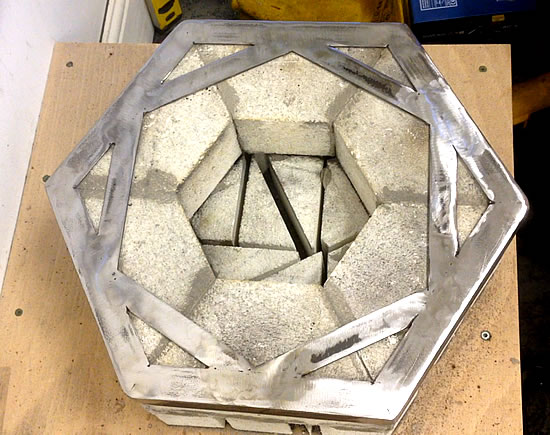
With these welded and grinded back, I added another row of angle iron in the same way but sitting on top of the first. This is welded securely to the frame below it, adding considerable strength. My thoughts originally were that this frame would rise and lower directly on to the blocks, but I changed my mind as I later discovered how fragile the bricks were.
I filled in the centre void with two more bricks and mortar, making sure everything was nice and flat. It was at this point I noticed I was already starting to lose the corners of the soft bricks, so the idea of the frame dropping onto bricks had to change.
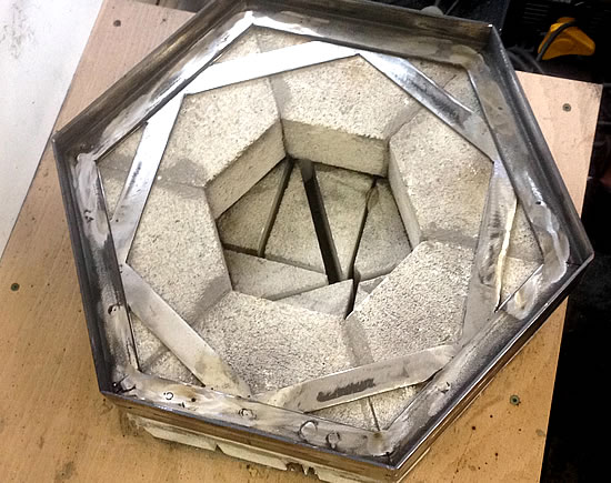
Frame 3
Taking some slightly smaller angle iron - 20mm (3/4 inch) - I made a frame that was exactly the same dimensions as the brickwork circumference. It fitted nicely inside the larger frame, but not too loosely.
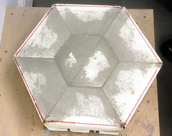
As this frame matched the sizeof the base perimeter, I centralised it and used a marker pen to draw around the inside. This showed me how much needed to be cut away so the frame cut simply slide over, a bit lile a ring around a barrel.
It's only a small slice that needs taking off and this can be done with hand tools – a saw, rasp or even sandpaper. I actually used a router with an old straight cutting bit, though a mask is essential there as a lot of dust is created.
With the edges cut to size, the edge of the frame was scored into the base with a sharp blade. This marked area needed to be removed just a little deeper than the thickness of the angle iron.
The frame was then be mortared onto the bricks, pushed on firmly and made flush to the surface, with all the gaps carefully filled.
Brackets
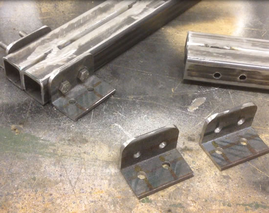
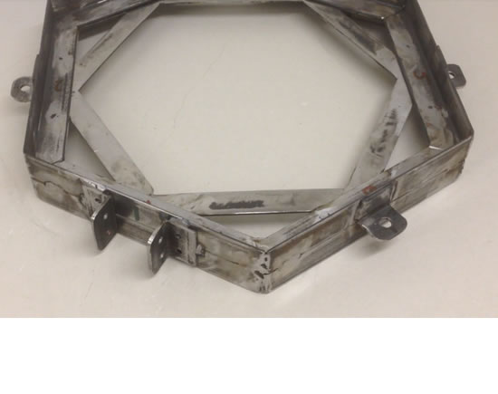
Whilst this was dying off for 24 hours, I returned my attention to the larger frame. I knew I needed some brackets added and I made these with more 30mm (1 3/8 inch) angle iron angle iron. I marked, drilled and cut these out, rounding the edges with my angle grinder.
I needed eight of these, measuring approximated 40mm (1.5inch) each with a 10mm (3/8 inch) hole.
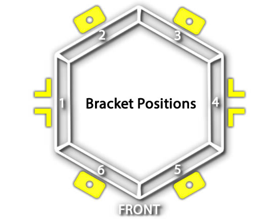
Four of these are welded to the frame, each in the centre of its side. To make life easier I numbered the sides and you'll see these markings throughout for conveniece. It helps ensure everything goes where it should.
I also made eight larger brackets, these being 50mm (2 inch) long with two 6mm (1/4 inch) holes drilled in them. I new these would be separated by two lengths of inch box steel (25mm), though I was uncertain about lengths at this point.
I made use of scraps to help me position and weld these on the frame. I gave the frame a quick clean to remove any welding splatter then gave everything a good coat of rust killer.
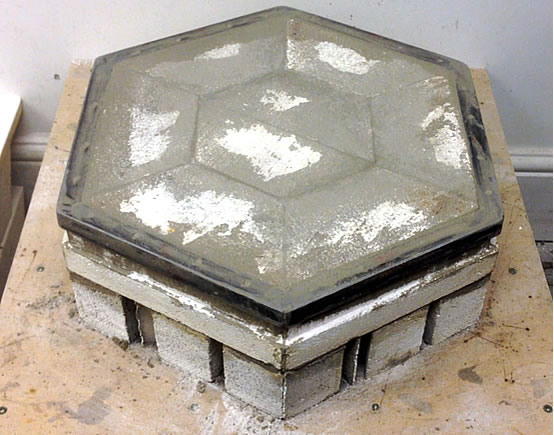
The next day, returning to the base, the large frame lowered nicely over the metal-rimmed base. Unfortunately thanks to welding, the frame had developed a slight warp. The weight of the bricks would easily cope with this but the frame would need to be held down with straps.
Recessing The Bricks
But before this, the first row of bricks would need attention. If the bricks are to sit flat upon the the base, the depth and shape of the frame needs to be recessed in each individual brick. As I wasn't very careful with my framework, I needed to make individual patterns for each brick. This is easily achieved with charcoal and paper with a simple bit of charcoal rubbing.
 With a router and a straight cutting bit, it's simple to recess the depth of the outer edge of the frame on each block, though this could also be done with a rasp or file.
Returning to the charcoal patterns, each is placed on a block and marked through with a sharp blade. It's worth rotating the pattern 180 degrees as this is in fact a mirror image of the frame.
With this done I glued some coarse sandpaper to a length of flat bar and used this to sand away the depth of each recess.
Whilst we're working on the blocks, it's time to recess the location of the coil and coils are big topic. So let's digress for a while and talk about resistance coils.
Coils
When considering coils, the length, type and thickness of the wire determine how much electrical resistance the wire carries. Generally, the thinner or longer the wire is, the higher the resistance. Similarly the shorter and thicker the wire is, the lower the resistance.
When electrical resistance occurs within a wire, heat is generated. If the wire is capable of handling heat for prolonged periods and the conditions are just right, it's possible to make the wire glow red hot - and that's what a resistance heating coil element is.
The Power of the coil is measured in Watts, with 1000 Watts being 1 kilowatt.
I made my coils from Kanthal wire using the coil making jig I've already shared with you. Ideally to make your own coils that meets your specific needs, you need to understand the electrical requirements and restrictions involved.
Voltage
Let's start with voltage. This is likely to be the mains voltage in your part of the world. Here in the UK for example, mains voltage is 230 Volts. In the US and Canada, I believe its 120 Volts. In Japan I believe it's 100 Volts. Whatever your region, you need to know this if you're going to make a coil.
Current
Next and to me most crucial is current. Remember it's current and not voltage that kills you so getting this right is critical. You must decide what sort of current levels you want your coil to draw.
It's VERY important that you determine the maximum current output of your outlet.
Again using the UK as an example, the average electrical outlet has a fused output of 13 Amps. As my foundry was going to be plugged into a UK outlet, I obviously needed a coil that would draw less than 13 Amps. Dropping to 12 Amps is still a little close to the mark for me, so I chose to draw only 10 Amps of power, staying 3 Amps below threshold. The closer I get to 13, the more likely I am to blow fuses and have electrical failures. The further I go from it, the weaker my foundry will be – because it's current that drives your foundry.
So you must identify the maximum current output of your outlet guys and you then drop down two or three amps for safety.


 Now a common problem associated with electric foundries is creep. This occurs with repeated heating and cooling of the coils which can result in areas sagging free of grooves as TAOW mentions in one of his videos. This is a safety issue because if the coil comes into contact with a graphite or steel crucible, the crucible will become live. TAOW cleverly fixed this issue with stables.